Being an IT engineer with wife, kid and mother, I am sure you would understand and forgive for this post after nearly 2 years

So much of parts and DIY stuff is packed in Boot that I almost forgot about it all. With driven around resulted in I nearly forgetting owning a car and driving

Enough of excuses and ....
My car had 7 switches in dashboard. 4 Dummy buttons and 3 factory fitted switches namely ESP, Defogger and Hazard
It was sore to look at these dummy switches. So wanted to change them to actual switches namely - Left Heated Seat, Parktronic, Auto On Off and Right Heated Seat and make them illuminate like rest.
Got 3 switches from NL from used car dealer and 1 brand new from Russia. Procured housing but they were not for individual with suffix A,B. So only inside connector could go in switches.
Here is how the pins are arranged.
1 - 4
2 - 5
3 - 6
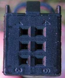
- 4D0971636-PIN.png (126.44 KiB) Viewed 6778 times
Above connector has flat and groove pattern on top and bottom.
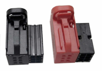
- SwitchWithTopBottom.png (82.74 KiB) Viewed 6778 times
viewtopic.php?f=56&t=64354&start=15#p540747 though mentioned which button needs to be fed power, I somehow stored pin 3 and pin 6 in my memory and kept on checking. I removed all wire connectors from the 4D0971636 except wire at 3 and 6.
To get desired output ie illumination, took one switch at a time and inserted connector and :
1. Checked if it illuminated. (Pin 3 +ve and Pin 6 -ve)
2. Reversed polarity and checked (Pin 3 -ve and Pin 6 -ve)
3. Reversed connector and checked (Pin 1 +ve and Pin 4 -ve)
4. Reversed polarity and checked. (Pin 1-ve and Pin 4 +ve)
To check all are working, I just checked if they illuminate but did not note down pins and polarity.
So ended up doing this exercise few times

This connector slides in plastic housing with notch displayed. Factory fittings has grooves on top.
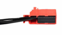
- SwitchInHousing.png (17.06 KiB) Viewed 6778 times
However in reality it goes upside down.
So if you get pin configuration right and then insert in cover to latch in switches, then all connections have become wrong
Anyway with enough playing like kid figured the pins.
Now the wiring --
Splices 05 sqmm wires at one end and then at desired length so I can join the wires from the switches. Made two of these one for +ve and one for -ve.
Then soldered wires, applied sleeves and then taped it with insulating tape and finally with Loom Adhesive Cloth Tape.
Finally with Loom Adhesive Cloth Tape.
Then started colour coding the housings.
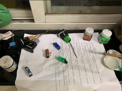
- ColorCoding.png (210.59 KiB) Viewed 6778 times
Dry Run
Dashboard Panel Removed
Music System, Climatronic and Cage Removed
Original Fuse Box
Route the wire from and into fuse box through holes that are used to lock fuse box cover.
The wholes are quite large. Single positive wire with all protection can easily routed inside.
Fuse box after tapping in Fuse # 7
Here are tapped fuse details
Negative wire is further router to right side of dashboard. Grounded created with a nut onto a metal body part.
Fuse box cover fixed
Finally this is how it looks during daytime.
This is how it looks at night or illuminated.
Very honestly illuminates images (shared here) does not do justice. The color looks orange here where are in reality they are Red. To match rest of interior.
Parts used :
- Soldering Gun for soldering Joints
- Sleeve to cover the soldered joints
- Insulating Tape wrapped for all joints
- Applied loom tape for whole wires. From dashboard to fuse box both wrapped together. Once split then covered individually.
A) 6R0963563 -- Left Heated Seat
B) 6R0963564 -- Right Heated Seat
C) 6RU927122 -- Parkrtronic
D) 6R0905218 -- Auto On Off
- Connectors used -- 4D0971636
So all experts please advise:
- 0.5 sqmm wire should be good enough? (though too late to ask)
- Tapped Original Fuse is 15A and I have used 10A for these switches.